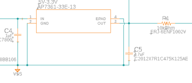
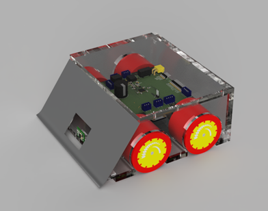
ME 507 Mechanical Control System Design
Robot Sumo Competition

Logan Williamson, Caleb Savard and Cole Marin

Robot Sumo Tournament


Introduction

ME 507 - Mechanical Control System Design is a project-based class for graduate students at California Polytechnic State University San Luis Obispo, CA. Over the course of eight weeks, five teams worked to design, build, program, and test their sumo robots. At the end of the design cycle, these prototype sumo bots were put head-to-head in the arena to wrestle against each other. Unlike Battle Bots, the object of a Sumo Robot match is not to destroy your opponent, but to push them off the circular dohyō. The first robot to touch the ground loses the match. Our competition was run as a bracket tournament, with each round of the tournament determined by the best of three matches. The tournament rules placed a number of restrictions on sumo robot designs to ensure an even playing field and attempt to demonstrate teams’ programmed strategy (rather than matches being determined by the mechanical design alone).

Table 1. Design Constraints
Mass (maximum) 1.5 kg
Bounding Box (maximum) 180 mm x 180 mm x 100 mm
Battery Voltage (maximum) 12.6 V (3S LiPo)
Battery Capacity (maximum) 17 Wh
Motor Size (maximum) ⌀ 25 mm x 32 mm (excluding gearbox)
Motor Quantity (maximum) 4
Motor Power (maximum, combined) 50 W

With these design constraints in mind, each team's robot was required to have the following components:


Mechanical Design

Per the requirements of this project, all sumo robots had to be manufactured using rapid prototyping techniques such as laser cutting, 3D printing, and waterjet cutting. To comply with this requirement and meet our manufacturing deadline, our team decided to use laser cut acrylic panels for the body of the robot. Acrylic was selected because it is easy to laser cut, durable, rigid, and cheap. The four panels of the robot body were modeled in Fusion 360 to visualize the design and ensure that it met the maximum space envelope specifications. This also gave us an accurate estimate of the frame’s overall weight, which was entered into our bill of materials for calculating the final maximum weight prior to ordering parts and manufacturing the design.

Sumobot CAD Render
Figure 1. Render of mechanical design CAD model.

Acylic Frame

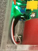
With the geometry modeled, the sketches used to drive the 3D modeled parts were then exported as DXF files for use on the laser cutter in the Mustang ‘60 machine shop. These cut panels were adhered together using JB Weld plastic epoxy. Epoxy proved to be a poor choice of adhesive, as it did not bond to the surfaces of the laser cut acrylic panels reliably. Several panel separations occurred between the baseplate and sidewalls of the robot body throughout our testing process. These issues were easily remedied using superglue and some 3D printed corner brackets, as we will discuss in more detail later in this report. Starting with superglue or proper acrylic welding cement would have been a better initial choice for our adhesive.

Mechanical Build Photo
Figure 2. Initial Structural Build

Acrylic presented the additional challenge of limiting the placement of fasteners and the type of fastener heads that our team could use to mount hardware to the robot body. Countersink fasteners could not be used due to the expansive force they place on the material they fasten, which is not conducive to reliable fastening of brittle acrylic panels. This limited us to higher-profile fastener heads such as button and hex, which caused issues with vehicle clearance when used to secure our motor mounts through the baseplate. These screw head profiles were too tall, causing the sumo bot to bottom out and reducing our traction. To address this issue, I used a manual mill to remove 3/16" from the lower standoffs of the motor mounts. However, when our robot pushed under another during testing, we were still bottoming out and losing traction to the scraping screw heads. We eventually had to rush-order low profile hex head screws to mount the motor mounts to the baseplate.

Bulldozer Blade

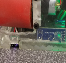
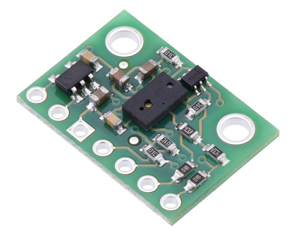
The front side of the robot was designed to be a thin piece of steel cut into a rectangle and bent at the lower edge to form a bulldozer-style pushing blade. A hole was then cut in this component to accommodate a time-of-flight sensor. Very few changes were made to this design from the first iteration; however, we were unable to manufacture this part using a waterjet, as it was not available until one day before the mechanical design deadline. To manufacture this component in time, our team simply used a manual shear to cut the rough shape of the blade, bent the lower edge in a brake-press, and filed the edges and corners to the proper final shape and dullness.

Our team needed the dozer blade and the cover of the robot to be removeable to maintain access to the internals of the robot. This was achieved by mounting both the blade and cover with fasteners rather than adhesives. We considered using inserts on our relatively thin acrylic, but ultimately our team tapped holes directly into the acrylic sidewalls for fastening of these removeable components. This decision also contributed to the sidewall separation from the baseplate during testing but was also resolved by the addition of the 3D printed components used to compensate for our poor adhesive selection. Mounting of the dozer blade in this later iteration of the design was done by heat setting M3 screw inserts into these 3D components to remove load from the sidewalls and prevent further separation of the frame panels.

Selecting Drive Components

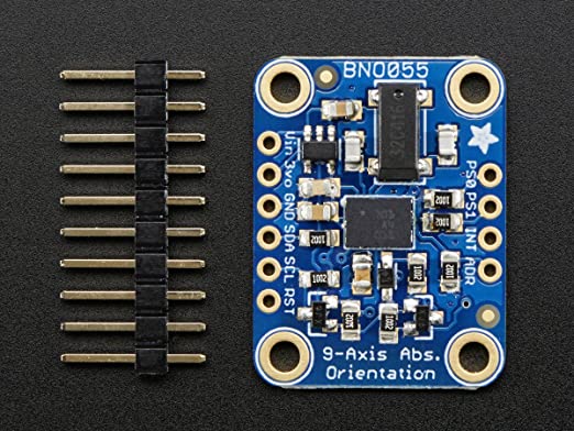
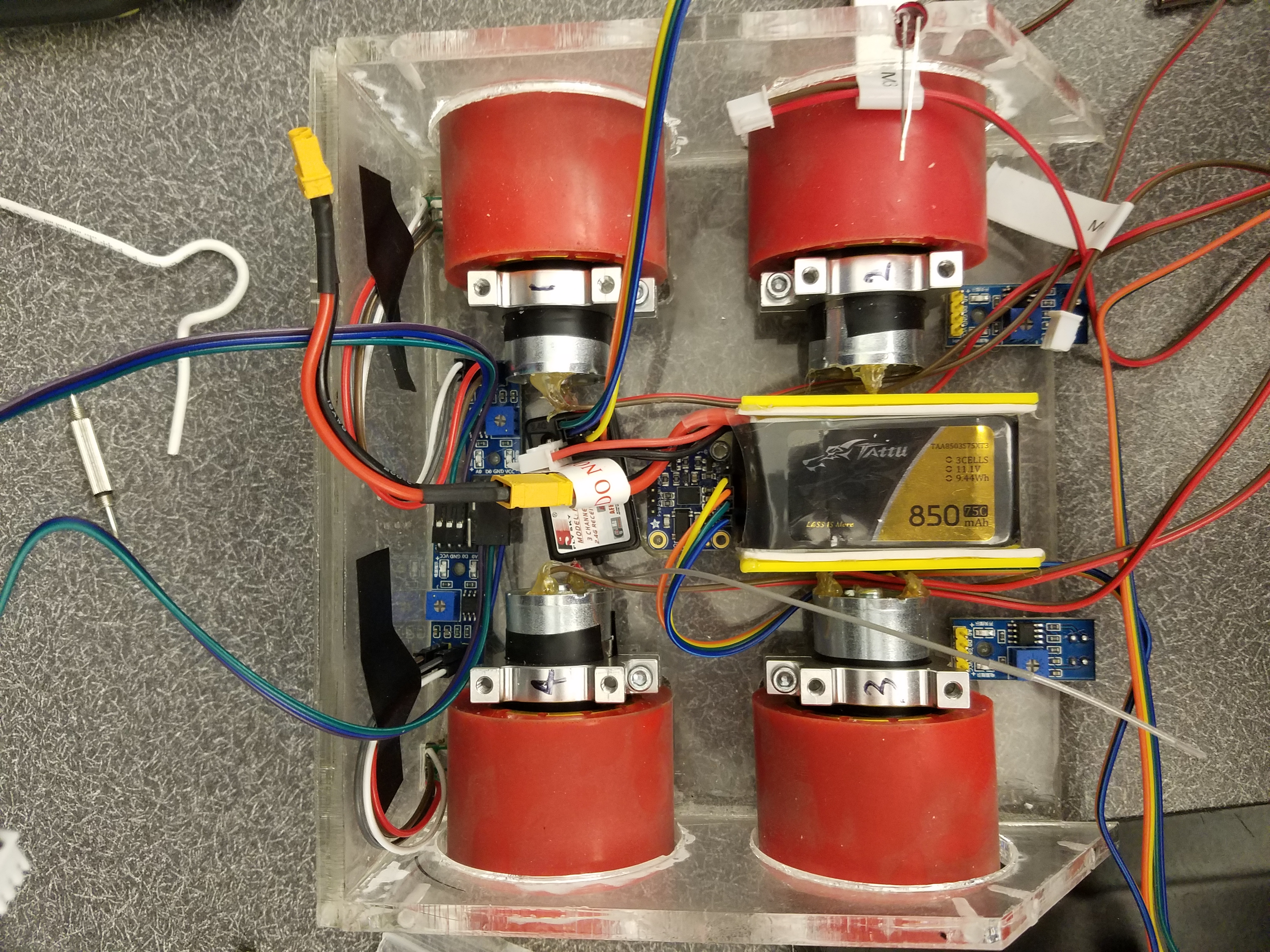
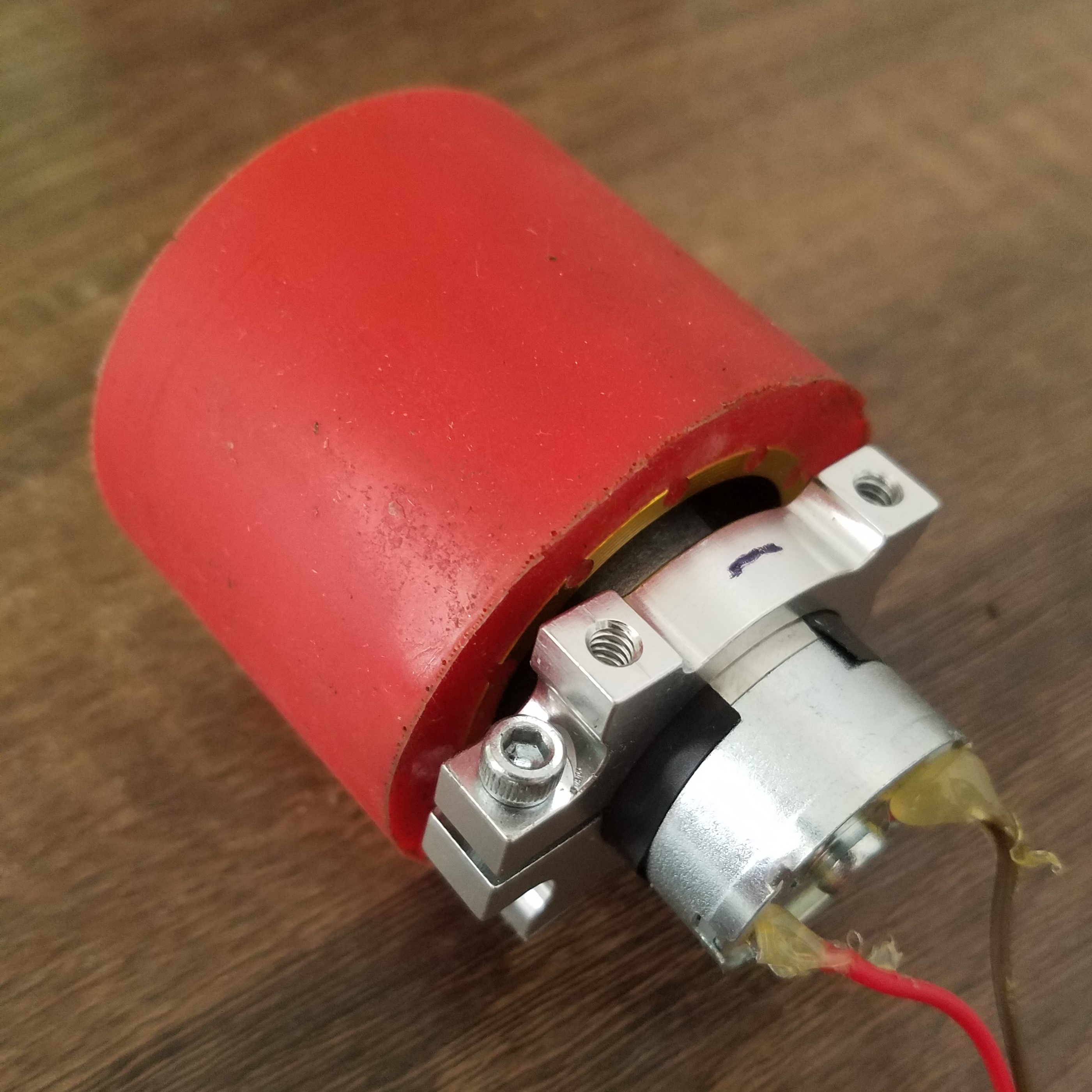
Throughout the mechanical design of this project, wheel and motor selection were critical topics of discussion as these components would determine the power transmission capabilities of our design. Our team decided to use Shore A20 polyurethane wheels purchased from FingerTech Robotics due to this material’s superior coefficient of static friction. The manufacturer claims that their polyurethane wheels provide greater friction than silicone wheels commonly used in robot sumo, µ = 1.75 for Shore A20 versus µ = 1.30 for silicone (on MDF particle board). Using this material coefficient of friction and assuming the maximum robot weight of 1500g, we calculated hat the maximum static friction force these wheels can support is 92.61 oz-in.

BOM
Figure 3. FingerTech Robotics ShoreA20 robot sumo wheels

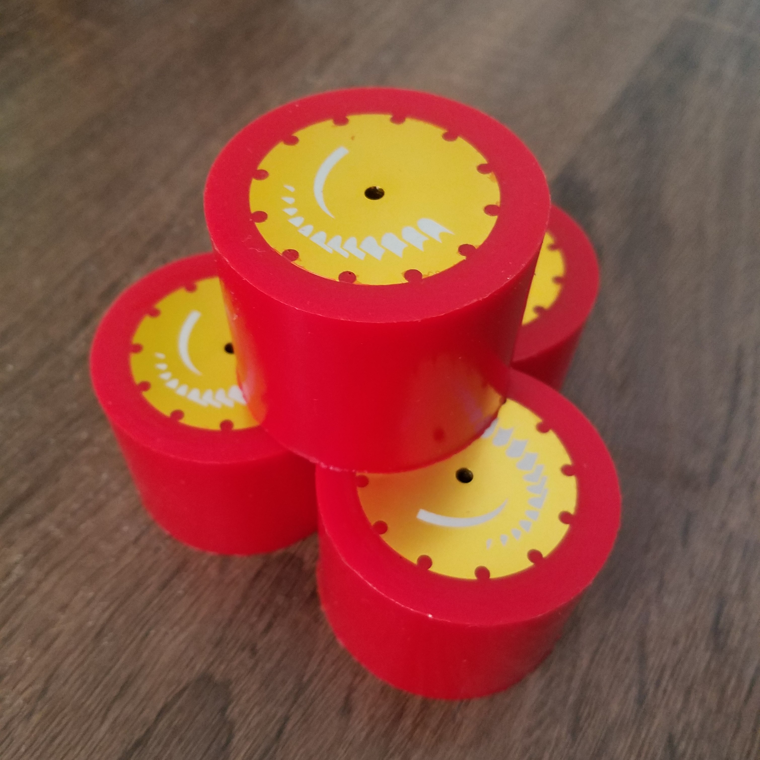
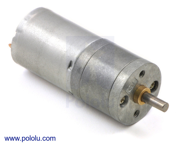
With this traction limit in mind, our team researched motors with a projected stall torque of 100oz-in, while considering the other motor specifications of 25mm maximum can diameter and maximum operating power output of 12.5W per motor. This ensured plenty of overhead to prevent our motors from approaching stall conditions assuming a maximum possible load of 93oz-in based on the traction limit of the wheels distributed among four motors. These constraints narrowed down our options to the 12V, 20.4:1 gearmotors from Pololu. Many other teams in our competition ended up independently selecting the same motors, some with slightly lower and higher gear ratios. This further solidified our confidence in the selection of these motors. The wheels from FingerTech Robotics had some issues with misaligned wheel hubs due to inadequate quality control by the manufacturer, but this problem was self-corrected as the motor shafts wore in the wheel hubs during testing. This wear did create a need for us to replace the set screws in these wheels with longer screws to prevent them from falling off when the robot made many consecutive turns. With these modifications, the wheels performed well in the competition. Our selected motors also performed well and caused no issues at any stage of our testing.

Gearmotor
Figure 4. Pololu 20.4:1 metal gearmotor

Drive System Mounts

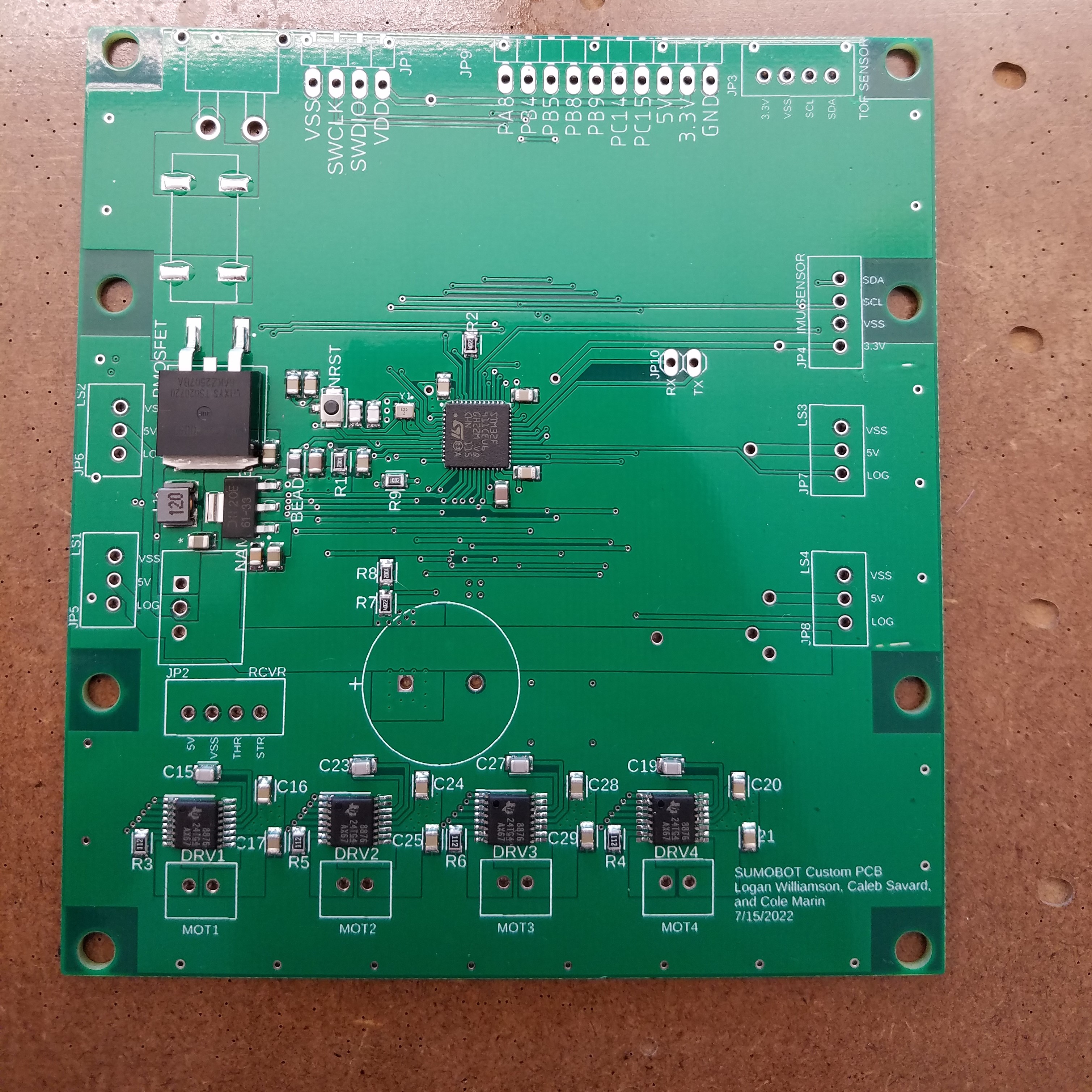
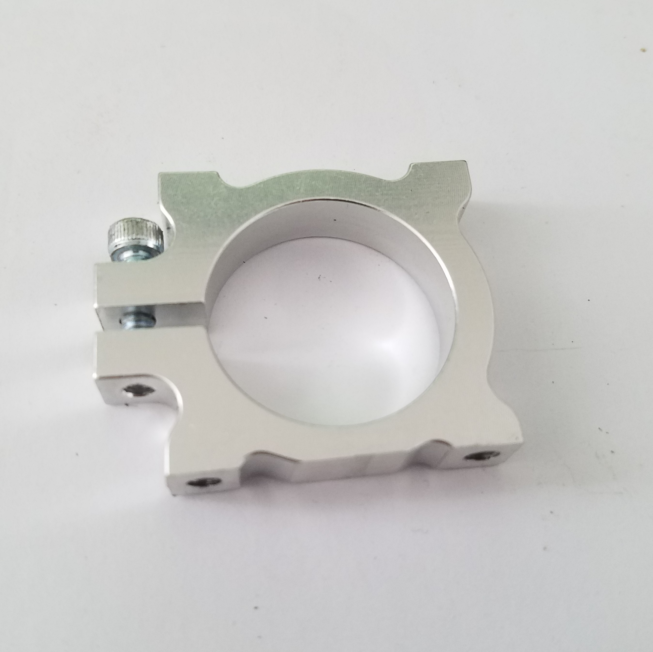
Finally, a method of mounting our motors needed to be selected. While we would have liked to 3D print custom motor mounts to provide additional frame support near the corners of the robot body, we did not have access to a 3D printer until quite late in the project. To avoid missing our deadline, we selected 25mm clamping motor mounts made from aluminum. These mounts were ideal for this type of motor but did require some minor modifications for our project. First, they did not provide sufficient dropout for our wheels, which meant we needed to reduce the height of the mount between the motor itself and the baseplate of the robot body. This was done by fastening all four mounts to a piece of Delrin which had been turned to 25mm diameter on a manual lathe. With all four mounts fastened as a common part, the lower-side standoffs could then be milled down by 1/8 inch to provide adequate wheel dropout and prevent the motor mount fasteners’ heads from dragging on the ground. Additionally, these mounts did not provide much stability against bending moments about the horizontal axis perpendicular to the motor axis. To support such moments, our team decided to incorporate our PCB as a structural component by mounting it to the top of these motor mounts. This proved inconvenient to our later wire routing efforts but did achieve the goal of supporting the motor mounts against bending moments.

Motor mount
Figure 5. Motor mount
Quarter drive
Figure 6. Drive module

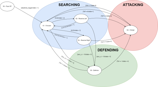
The final drive system for our sumo bot consists of four independent drive modules, enabling various ways to define skid-steering PWM signals for the whole system despite having four relatively wide wheels.

Results

Final CAD
Figure 7. Final prototype CAD model

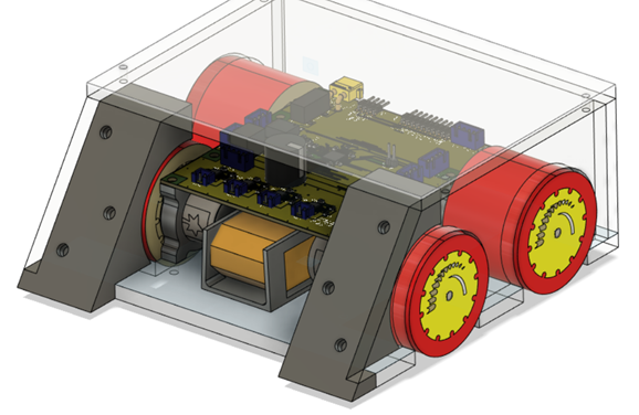
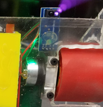
As the project progressed, three new components were created to address issues that arose with the mechanical design. As mentioned previously, the acrylic sidewalls split away from the baseplate due to a hard impact during testing. This was remedied with superglue and the addition of 3D printed components (as seen in Figure 2) which served to support the sidewalls and provide a more durable mounting solution for the dozer blade on the front of the robot. Concerns about potentially damaging the battery led us to 3D print a small battery holder which was epoxied to the baseplate of the frame and lined with foam. Finally, a small time-of-flight sensor mount was 3D printed and adhered to the back of the dozer blade rather than directly mounting the sensor to the baseplate of the frame. This provided a better vantage point for the sensor and kept it farther out of harm’s way during matches. With these small additions, the final mechanical design proved to be durable and effective during testing and the competition. The robot could be driven off the side of the dohyo and crashed into other robots without any further mechanical failures. The selected wheels and motors exceeded our performance expectations; they could push a wheeled office chair with a person in it across the lab, a test which other teams were unable to replicate using their own robots.


Electrical Design

The other major design aspect of this project was the printed circuit board (PCB) design. This design was performed in tandem with sensor selection, as routing and wiring headers needed to be included for each device the board would connect to. Early in the PCB design, we identified the need for a 12V, 5V, and 3.3V power rail. The 12V rail would obviously power our 12V gearmotors and would provide some basic battery safety features to prevent damage to the PCB or battery. The 5V rail was used to power our RC car receiver and our digital reflectance sensors used for detecting the arena lines. Finally, the 3.3V rail was used to power our STM32F411CEU6 microcontroller, our inertial measurement unit, and our time-of-flight sensor.

Fusion 360 PCB CAD
Figure 8. Custom PCB
JLC PCB
Figure 9. JLC custom fabricated PCB

Protection Circuitry

The 12V rail was designed to be powered by an unregulated Tattu 11.1V (nominal), 850mAh lithium polymer (LiPo) quadcopter battery. To connect this battery, our instructor provided us with a male XT-30 connector for mounting on our PCB. This connector provided our primary ground reference, as well as the input power to our protective circuitry ‘upstream’ of the actual 12V power rail. For circuit protection, we included a 10A automotive blade fuse and holder to prevent short circuiting of the battery terminals via a replaceable fuse. Reverse polarity protection is then provided by a IXTA24P085T P-type mosfet. This prevents current from flowing if the user somehow manages to connect the battery with incorrect polarity. This mosfet was chosen for its large, easily mounted package size and its high current and voltage ratings.

12 Schematic
Figure 9. Overdraw and polarity protection circuitry schematic

12V Motor Power Rail

The output from this P-mosfet is then routed via an internal 12V power polygon on layer 2 of the board to four Texas Instruments DRV8876 motor drivers. These drivers can provide up to 2.5A of current to each motor in our design, with transient peak currents of up to 3.5A if we decided to use a larger capacity fuse. They were selected primarily for their current and voltage handling capabilities, as well as their Isense output which allows the user to read the scaled current draw of each motor using the microcontroller analog to digital converter (ADC). Additionally, they are quite easy to use, allowing the user to control motors with either traditional PWM inputs or a single PWM input and a GPIO direction control input.

12 Schematic
Figure 10. Schematic of one DRV8876 motor driver. The pullup resistor and decoupling capacitor, seen in the left side of the image, were selected based on the typical application circuit recommendations from the Texas Instruments datasheet provided for this driver. All inputs and outputs that could be shared between drivers, such as enable pins and fault outputs, were tied together to minimize the number of MCU pins devoted to motor driving.

As seen in the schematic of Figure 4, the fault outputs from all four drivers are tied together, as are the enable/SLEEP_N inputs, and the VREF reference voltages for driver control. This provides the benefit of consistent operation across all four drivers but does present potential troubleshooting concerns such as the inability to differentiate between which motor driver causes a fault condition. This was done for the sake of minimizing the number of microcontroller pins dedicated to motor drivers, and fortunately did not cause any issues.

5V Receiver and Line Sensor Rail

The 12V power rail is then routed to a RECOM R-78E5.0-1.0 switching regulator, as seen in Figure 11. The R-78E5.0-1.0 was selected because it is a drop-in replacement for linear regulators but provides the thermal management and efficiency of a switching regulator. Many other switching regulators were considered, but most had anywhere from 4-16 pins that needed to be properly connected. This device has only three pins: GND/VSS, 12Vin, and 5Vout. This made it a remarkably simple package to work with, which still provided the 1A of output current required to power all subsequent 5V and 3.3V devices with some overhead. The 5V rail powered both our receiver and the four digital line sensors in our design. The JSumo ML2 line sensors we had specified were unfortunately limited in stock; however, another team had purchased 10 similar line sensors and graciously offered to let us use their extras, which worked on the same input voltage and provided the same type of digital output. These line sensors worked well and would later form the basis of a sizable portion of our control scheme. The receiver/transmitter combination our team selected was the FlySky GT3A package. This was a standard receiver, requiring 5V input and providing two timer outputs, one for the steering control channel and the other for the throttle control channel. These inputs were easily captured by a properly configured timer for later scaling and calculation of corresponding motor commands.

12-5 buck schematic
Figure 11. 12-5V switching regulator with auxiliary circuitry. A 12uH inductor prevents rapid inrush of current which could damage the regulator. Decoupling capacitor values and smoothing inductor values were selected based on typical application circuits from the R-78E5.0-1.0 datasheet.

3.3V MCU and I2C Sensor Rail

Finally, the 5V rail powers a Diodes Incorporated AP7361-33E-13 low-dropout linear regulator which shifts the voltage down to 3.3V for use by our microcontroller and the remaining sensors, as seen in Figure 12. All sensors were purchased already mounted on breakout boards containing the additional circuitry specified for those sensors. These components were connected to the PCB via standard DuPont connectors on the breakouts, and JST connectors on our PCB design. This allowed for unidirectional connection of wiring harnesses and helped us keep consistent color coding across wiring harnesses for similar sensors.

5-3.3 buck schematic
Figure 12. Low-dropout linear regulator circuit. Decoupling capacitors were selected based on typical application circuit from Diodes Incorporated datasheet.

Reset Circuitry

Two other major pieces of circuitry were required for this PCB design to function properly. Namely, we were required to include a way to reset the microcontroller, and we were highly encouraged to include an external crystal oscillator to provide a higher frequency clock signal than the internal oscillator of the STM32F411CEU6 can provide. The reset circuit was simple to design. A button is used to drive the nRST pin of the microcontroller to ground when it is pressed; when the button is not pressed, the nRST pin of the microcontroller is held at 3.3V. This circuit can be seen in Figure 13.

NRST schematic
Figure 13. Reset circuit. Input to the nRST pin on the microcontroller is represented by the vertical net at the top of the image. This net is held at 3.3V, current decoupled from the 3.3V rail by resistor R1, until the NRST button is pressed. When the button is pressed, the nRST pin of the microcontroller will be shorted to ground, resetting the device. Resistor R1 prevents excess flow of current from the 3.3V rail to ground when the button is pressed.

Crystal Oscillator Circuitry

The clock circuit was similarly simple to design by following recommended circuits in the STM32F411CEU6 datasheet. To achieve an adequately precise 96MHz phase-locked loop (PLL) clock signal, our microcontroller’s internal oscillators are insufficient. In the interest of avoiding issues with our clock signals, we specified a 25MHz ECS-250-9-37B2-CKM-TR crystal oscillator. This signal can easily be upscaled to provide a proper 96MHz clock signal via PLL methods. The circuitry for connecting this oscillator to the microcontroller can be seen in Figure 14.

CLK schematic
Figure 14. External crystal oscillator circuitry. This oscillator required two 8pF decoupling capacitors between the PH0-OSC_IN and ground, and PH1-OSC_OUT input and ground. These values were calculated based on a load capacitance of 9pF from the device datasheet, and assuming a stray capacitance of 5pF, using the equation:

C_load= (C_1 C_2)/(C_1+C_2 )+ C_stray

where C1 and C2 are the decoupling capacitors to specify.

Sensor Selection

While not all our peripherals worked effectively on competition day, we outfitted our sumo bot with many sensors to gather as much data as possible during the match. During our first week of planning our design, our group came to the decision that the line sensors would likely be the most crucial sensors that our robot would incorporate, since, without effective edge detection, our bot would simple run itself off the dohyo. Therefore, we originally chose to order four ML2 dual micro line sensors from robotshop.com due to the fact that they only require that we allot one digital logic pin per sensor. Additionally, each ML2 line sensor board contains two independent line detectors that must both be high or low to trigger the respective signal. Unfortunately, we were never able to implement these sensors in our design as they went out of stock before we were able to place our order. Another group was kind enough to donate four of their line sensors to us instead, which were similar to the model that we originally chose. These sensors were, however, significantly larger than our original design, and would not fit as we intended. To accommodate this, we modified the sensors, mounting the IR transducer remotely with wires running back to the sensor’s main PCB, as shown in Figure 15.

LS left
LS middle
LS right
Figure 15. Line sensor in the off-the-shelf configuration, used for the two front corners of our design (left). Line sensor with the modified remote IR transducer, used on both rear corners of our design (middle & right).

With edge detection covered, our group felt that collision detection would be a useful tool to aid in our overall strategy. We implemented an on-board IMU as well as current sensors to accomplish this. Fortunately, Charlie was able to loan our group a BNO055 IMU that has been proven to work effectively in his other classes and proved similarly reliable in our testing. While this sensor is capable of providing a variety of data including magnetic field strength, temperature, and local gravity, we mainly used this sensor to detect spikes in lateral acceleration due to side impacts from other bots as well as heading. We also originally intended to detect acceleration spikes in the forwards and backwards directions, though we quickly discovered through impact testing that the acceleration of our bot due to simply driving forward exceeded that of collisions in the same direction. Due to the orientation of the wheels, front or rear collisions seemed to show a spike in acceleration that was smaller in magnitude than side accelerations, which we found to be roughly 16 m/s2 and 21 m/s2, respectively. Fortunately, we had marginally more success detecting front and rear impacts from our current sensor, which was a built-in functionality of our motor drivers.

For detecting the opponent at a distance, we selected a time of flight sensor. First, we ordered a VL6180X since it was readily available from same company our motors came from. On further research, we learned that this model is limited to about 60 cm of range. In hopes of exceeding this, we ordered a VL53L0X, which is good for up to 2 meters. Rather than using it to actively search for the opponent, we intended to use the Time of Flight sensor to set a flag if it detected a target within a certain threshold. This flag would be used to transition the robot into the charge state. We hoped this would keep the robot moving, preventing it from being blindsided while searching for the opponent, while still being able to react if the opponent entered its sights. In the end, we were able to get both time of flight sensors working at the testing bench.

Results

Overall, the electronics design worked reasonably well and was able to drive our motors and sensors without major electrical issues. We did experience a phenomenon where our I2C communication worked perfectly at the testing bench but appeared to fail whenever our motors reversed direction rapidly. We believe this may be due to electromagnetic interference (EMI) issues, possibly connected to routing of two perpendicular I2C traces directly above one of the motor cans. Our working theory is that this distorted the I2C signal enough to cause the STM Cube IDE hardware abstraction layer (HAL) I2C protocol to register a fault and enter the fault handler. We made numerous efforts to replicate this issue at the workbench but were unable to capture anything other than perfect I2C datagrams on the oscilloscope. It is entirely possible that the issue lies elsewhere in our code for driving the I2C sensors, or in the HAL itself. The EMI considerations paid to this design were lacking in either case. If we were to revisit this design, we would consider EMI issues much more diligently when it comes to our component placement and routing.


Programming

While good hardware is certainly important for a Sumo Robot, a clever program is critical to making best use of the robot’s physical capabilities. While our team had past experience with Python, the project was required to be written in C or C++, languages largely new to all of us. Despite the steep learning curve, we grew to appreciate the speed and versatility of C for embedded applications like this.

All code for this project was written using the STM32 CubeIDE. This tool is designed for use with STM32 microcontrollers, and gives the user access to the STM Hardware Abstraction Layer (HAL) which can be used to automatically generate code for abstracting away low-level management of the chip in favor of high-level control tools. This was particularly useful for timer configuration, pin initialization, and serial communication management. STM's HAL greatly simplified the chip setup, and provided tools for interacting with our hardware throughout this project. Though this environment is designed for C, and the introduction to CubeIDE was presented to the teams in C, we decided to use C++ because it allows for object-oriented programming and provided the extra challenge of learning how to implement C++ classes in two weeks. Since our whole team had more previous experience with Python than C, we decided this would be both a challenge, but also useful when the time came to utilize objects of our classes in the main program.

Texas Instruments DRV8876 Motor Driver

The driver class for controlling the motors consists of 3 methods. Enable and disable methods write the enable pins high and low, respectively. All four motor driver enable inputs are tied to the same MCU pin, meaning all motors can be enabled or disabled simultaneously using the enable/disable methods of any motor object. Control of each motor object is done by a method for setting the motor operating level. It accepts a signed 32-bit integer, saturates it outside of the ±4800 range, then controls the PWM duty cycle and direction pin accordingly. A motor level of 4800 corresponds to full speed, with the sign representing forward or reverse.

TI DRV8876
Figure 17. Texas Instruments DRV8876 motor driver IC

TCRT5000 Infrared Reflectance Sensor

The reflectance sensors we used in this project were very simple digital output sensors with a potentiometer on each breakout board for sensitivity tuning. Programming these sensors was as simple as setting up four GPIO input pins on our microcontroller. We managed these line sensors using a class, which allowed us to easily check which line sensors are triggered in a given moment from our main program logic.

Line Sensor
Figure 18. TCRT5000 reflectance sensor

FlySky GT2 Receiver

The radio receiver is used to relay a safety shutdown signal if the sumo bot operator releases the deadman's switch trigger during a match. This makes it critical that the receiver class functions quickly and reliably. We used the HAL’s built-in input-capture callback which triggers on every rising or falling edge of the input signal. The receiver transmits commands using pulse-width, so on the first edge, when the input signal is high, the callback stores the current timer value and sets a flag to record that the first edge has occurred. On the second edge, when the signal is low (the falling edge), the callback records the timer value again, calculates the difference (accounting for rollover), and clears the flag. This was challenging to program because any rising or falling edge on any of the two input channels would trigger the interrupt. To accommodate for this, the callback first checks which channel was ‘active’ when the callback triggered, a convenient feature of the HAL.

Receiver
Figure 19. FlySky GT2 receiver and transmitter

Adafruit BNO055 Inertial Measurement Unit Carrier

Fortunately, we were able to find a STM32 compatible driver for the BNO055 IMU that worked as expected with the rest of our code. A few tweaks had to be made to integrate the code with HAL; however, once those changes had been made and the I2C bus had been configured properly, we were able to consistently call functions such as bno055_getVectorEuler() and bno055_getVectorLinearAccel() which returned a heading vector and a linear acceleration vector, respectively.

While the IMU worked consistently most of the time, we did encounter an issue where it would “latch” onto seemingly random values on start-up and cease to get new readings. This issue could be related to the I2C issue we encountered with our time-of-flight sensor, though we were unsuccessful in diagnosing the problem nor the cause of the behavior. Luckily, the BNO055 IMU is equipped with an active-low reset pin that we were able to use with one of our GPIO outputs. By simply switching that pin low for 10ms before the sensor is initialized, we were successfully able to eliminate the issue.

IMU
Figure 20. Adafruit BNO055 inertial measurement unit breakout board

Pololu VL53L0X Time of Flight Sensor Carrier

The VL53L0X time-of-flight sensor is produced by ST, who has provided an API for interfacing with the sensor via I2C. Documentation is somewhat lacking and register addresses have not been made available, so this API is crucial to working with this sensor. Instead of ST’s API, we used one by Adafruit which is significantly lighter, if less powerful. This API is mostly self-contained. One file contains functions for writing to and reading from I2C registers, which are called from the rest of the API to perform various actions on the sensor. To make the API work for our application, we had to rewrite these functions to work with the HAL. For organization, we created a class for the time-of-flight sensor with a single method for getting the range. We intended to place all the setup and calibration code for the sensor inside the class’s constructor. This proved to be troublesome, as some of the setup code simply wouldn’t run if it wasn’t directly in main.cpp. We tried placing it in the constructor class, and in a separate function, but ended up leaving it in main.cpp due to time constraints. For maximum reading speed, we set the time-of-flight sensor to a mode where it continuously takes readings, starting the next one as soon as the last one is finished. To prevent blocking while the sensor is converging on a range, the ‘getRange’ method first checks if a measurement is currently available. If so, it updates a flag variable with the new range. Otherwise, it leaves the range flag unedited.

TOF_carrier
Figure 16. VL53L0X time-of-flight sensor breakout board

Main Program Logic

The logic for our sumo bot that encapsulated our strategy operated within three pseudo-states – searching, defending, and attacking. Our finite state machine did not transition between these modes explicitly, rather their purpose was to serve as a higher-level interpretation of what the goal of the sumo bot is at any given moment. Within these larger modes are the individual states that are mutually exclusive and transitioned between when certain data is received from the sensors.

When the robot put in autonomous mode after being powered on or reset, State 0 is automatically entered and no commands are given to the peripherals until the Deadman’s switch is triggered on the remote control. At this point, the robot enters state 1 and begins moving forward at a moderate speed while constantly calling tasks to get data from the line sensors and time of flight sensor. If the front right line sensor is triggered, the robot will reverse left in an arc until the rear left line sensor is triggered, at which point it will return to State 1. An opposite command will be given to the motors if the front left line sensor is triggered. This method of reversing until the line sensor on the opposite side is triggered causes the sumo bot to re-enter State 1 roughly perpendicular to the edge of the dohyo, which is optimal for spending as much time as possible close to the center of the arena. However, if the robot is in State 1 and the time-of-flight sensor registers an object within 0.5m, the motors are set to move forward at full speed in an attempt to push the opponent out of the ring. If the time-of-flight sensor no longer detects an object, the program reverts to State 1.

Lastly, our robot can enter a defensive state if the IMU registers a lateral acceleration greater than 15 m/s2 in either direction. Depending on whether the impact was detected from the left or right side of the robot, the sumo bot will reverse right or left, respectively, in order to move out of the way and align the front of the robot with the opponent. At this point, the program will enter State 4 if the time-of-flight sensor registers an object, otherwise it will simply revert to State 1. A complete state transition diagram can be seen below in Figure 17.

Finite State Machine
Figure 16. State transition diagram for the main logic of sumo bot program

Unfortunately, due to time constraints and intermittent issues with I2C communication, we opted not to use data from the time-of-flight sensor nor the IMU to inform our finite state machine. This forced our program to stay within the “searching” pseudo-state, blindly searching for opponents.


Project Results

Competition Outcome

Ultimately, our group was very pleased with our sumo bot’s performance in the competition, as we took first place in the bracketed competition and even won the “free- for-all” style match afterwards. That said, we attribute our bot’s success more to the overall mechanical design and motor choices rather than its collection and interpretation of data or general strategy.

Project Strengths

One of the most effective and unique elements of our sumo bot was our wide wheels, which offered excellent traction against the steel surface of the dohyo. The Shore A20 polyurethane that comprised our tires contributed to this success as well. Furthermore, our four DC motors were chosen to provide the right balance of torque and speed, the former of which proved to be much more important as many of our bouts quickly turned into pushing matches that were easily won. Another crucial component of our design was the front “dozer blade,” which allowed us to consistently get under our opponents, increasing the frictional force between our wheels and the arena while decreasing that of our competitor. Being able to adjust the height of the blade on the fly paid off as well, as we were able to make adjustments between matches to ensure our opponents would not be able to get under us. Lastly, with the exception of the wheels, the structural and electrical integrity of our robot seemed to be sufficient as neither our physical frame nor our PCB seemed to be affected by the impacts sustained by the other sumo bots.

Project Shortcomings

While we were ultimately content with our design, there were several areas that could have been improved if we were to revise our design. Firstly, while our acrylic sidewalls fared well when subjected to impacts during the competition, they were very difficult to tap into for fasteners. Using sheet metal instead may have relieved this issue and would have likely increased our overall structural integrity. During testing, we also found that we frequently needed to access the battery to unplug it. This was particularly difficult to do with the dozer blade preventing access to the battery holder located just on top of the baseplate of our sumo bot. Implementing a longer XT30 adapter that allows for easier access would have made our design much more convenient to work with. Furthermore, we had some issues with our wheels occasionally falling off the motor shaft despite tightening the set screws with plenty of torque. Using longer set screws that we were able to find in the lab, we were able to mitigate this issue enough to perform effectively during the competition. Lastly, and most notably, our I2C bus major issues that ultimately caused our time-of- flight sensor to fail. We assumed that this was caused by potential EMI but were unable to properly diagnose the issue.